
New Zealand Road Side Barrier System Standard Guide
1. NON-PROPRIETARY ROAD SAFETY BARRIER SYSTEMS
1.1 Semi-Rigid Roadside and Median Barriers
Semi-rigid barrier systems approved for use on state highways are shown in Figure 1 and 2: Semi-Rigid Roadside Barriers.These systems are described and detailed in the AASHTO-AGC-ARTBA Joint Committee. Subcommittee on New Highway Materials, Task Force 13 Report:A Guide to Standardized Highway Barrier Hardware – May 1995(Task Force 13 Report).
|
Task Force 13 Report Reference |
NCHRP Report 350 Test Level |
Type |
Post Spacing (mm) |
Deflection ( under highest impact severity) (mm) |
|
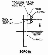
SGR04b (W-Beam) |
TL-3 |
|
1905 |
800 |
|
|
|
Figure 1:Semi-Rigid Roadside Barriers |
|
|
|
Task Force 13 Report Reference |
NCHRP Report 350 Test Level |
Type |
Post Spacing (mm) |
Deflection (under highest impact severity) (mm) |
|
SGR09c ( Thrie – beam ) |
TL-3 |
|
2000 |
680 |
|
SG09b (Thrie-beam, with modified blockout) |
TL-4 |
|
2000 |
600 (2000 kg pick-up) 900 (school bus) |
|
|
Figure 1(continued): Semi-Rigid Roadside Barriers |
|
||


|
Task Force 13 Report Reference |
NCHRP Report 350 Test Level |
Type |
Post Spacing (mm) |
Deflection (under highest impact severity) (mm) |
|
SGM04b (W-Beam) |
TL-3 |
|
1905 |
600 to 1200 |
|
SG09b (Thrie-beam, with modified blockout) |
TL-4 |
|
2000 |
300 to 900 |
|
|
|
Figure 2: Semi-Rigid Median Barriers |
|
|


1.2 Rigid Roadside and Median Barriers
(a)F-Shape Concrete Barrier
 Task Force 13 Report Reference:SGM10a-b Task Force 13 Report Reference:SGM10a-b |
 |
|
Median/Roadside Barrier NOTE:When used as a roadside barrier overall mass and dimensions must not be reduced.For ease of construction roadside barriers may use the optional constant rear slope cross-section. |
Roadside Barrier (Optional Constant Rear Slope Cross-Section) |
|
Figure 3: F-Shape Concrete Median and Roadside Barriers |
|
The F-shape concrete barrier system is shown in Figure 3 above.It is also described and detailed in the AASHTO-AGC-ARTBA Joint Committee, Subcommittee on New Highway Materials, Task Force 13 Report:A Guide to Standardized Highway Barrier Hardware – May 1995: System Drawing SGM10a-b.
For New Zealand state highway use the“INTENDED USE”and“COMPONENTS”paragraphs on Sheet 2 of SCM10a-b shall be replaced with the following:
INTENDED USE
The F-shape median barrier is similar to the more common New Jersey shape but the breakpoint is 80mm lower.The barrier has been successfully crash tested according to NCHRP Report 230 and has performed well in the field. Four reinforcement bars are shown but other sizes, numbers and arrangements of reinforcement have been used by state road controlling authorities in the US.The upper longitudinal reinforcement does not provide flexural strength, since it lies on the neutral axis, and it is only intended to prevent large pieces of the barrier breaking off and falling into the traffic lanes in the event of an impact.Additional flexural reinforcement will increase the strength of the barrier in severe impact situations.
A 3m long 250mm deep reinforced anchor footing must be provided at both ends, to properly secure the barrier.Other common methods of supporting the barrier include setting the barrier in a continuous keyed foundation or dowelling the barrier to a foundation.
A top-width of 200mm is usually adequate but some state road controlling authorities in the US have used a top-width of 240mm, to accommodate sign and luminaire supports.
The barrier may be cast-in-place, slip formed or pre cast.Cast-in-place and slip formed barrier will normally be a continuous pour without transverse contraction joints.Cast-in-place segments less than 12m in length must be joined to adjacent sections by at least three 25mm diameter steel dowels, or an equivalent joining method approved by Transit New Zealand.
COMPONENTS
Concrete used in the construction shall comply with the requirements of NZS 3109 and shall be manufactured in accordance with NZS 3104.The minimum concrete cover depth is 40mm.The 28 day compressive strength and concrete binder type shall be in accordance with the durability requirements of NZS 3101 for the relevant exposure classification but in all cases shall be a minimum of 30 MPa.
Reinforcing steel shall be grade 500E or 500N conforming with AS/NZS 4671 and increased from 15 mm to 16 mm.”
